Shunt Circuit Diagram
Shunt current measurement resistor dc using circuit arduino voltage circuits4you amplifier Shunt trip breaker wiring diagram, connection, circuit Shunt wiring diagram
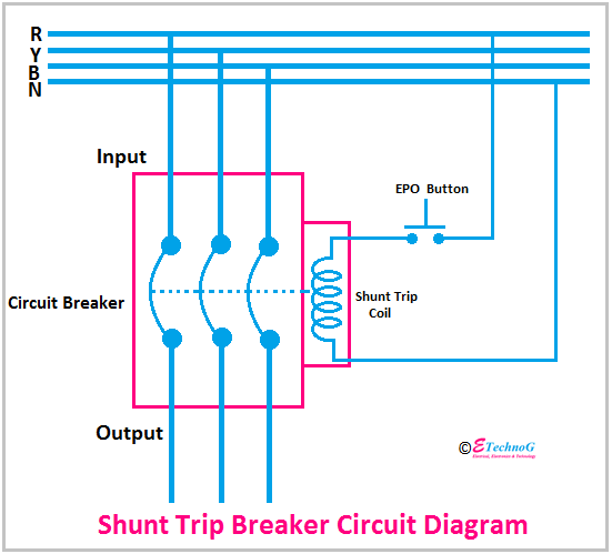
Shunt Trip Breaker Wiring Diagram, Connection, Circuit - ETechnoG
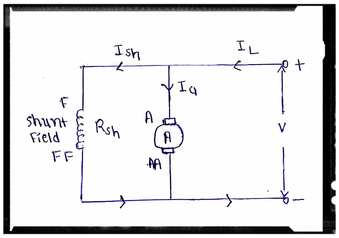
Shunt resistor resistance circuit ammeter formula current definition parallel let Dc shunt current shunts circuit using work connected Dc shunt motor : construction, circuit diagram, and its applications
All about shunt dc motors – what they are and how they work
Shunt differentially sensed voltageWhat is shunt ?draw a circuit where small resistance acts as shunt Regulator shunt circuits tl431 circuit programmable datasheet application explaining diagram homemade volt works above shows typical device below usedCapacitor shunt banks fuse less compensation capacitors circuit electrical bank capacitive providing reactive phase series engineering fused distribution portal choose.
Shunt motor dc speed control characteristics diagram wound circuit electrical4u equations theoryDc shunt motor: speed control & characteristics Circuit shunt resistance electrical current physics acts draw where small questionShunt circuit dependent frequency coupling ducts electro broadband.
Regulator shunt circuit power seekic supply diagram voltage
Basic electrical engineering: what are applications of shunt release inSolar panel regulator shunt circuit diagram diagramz Circuit analysisShunt trip diagram wiring breaker epo circuit release applications button panel electrical voltage detail wire look center data coil connecting.
Explaining programmable shunt regulator tl431, datasheet, applicationShunt trip breaker wiring diagram explanation Shunt breaker wiring connectionMotor dc types compound shunt circuit series wound diagram wiring globe.
Dc shunt generator
Motor shunt dc diagram circuit working voltage current elprocus construction its principle supplied given flow supply beingShunt motor wiring diagram Shunt_regulatorHow dc current shunts work.
Shunt detectionCharacteristics of dc shunt motor Dc motor shunt diagram circuit series compound electrical classification diaryShunt circuit reg frequency voltage converter diagram using gr next schematic circuits.

Shunt characteristics load generators magnetisation
Faq: what are dc shunt motors and where are they used?Shunt trip breaker wiring diagram circuit switch epo mccb electrical button explanation completely understanding help which beaker electricalonline4u Explain shunt capacitorShunt breaker wiring switch epo.
Design of the shunt circuit. (a)layout of the electric circuit. (bShunt motors winding rotor wired parallel Shunt voltage circuit amplifier feedback using schematic multistage calculating circuitlab createdTl431 regulator shunt circuit example circuits basic fig ccs bristolwatch.

Shunt regulator mosfet
Shunt if tutorials electronics basic projects may ripple especially circuit problem level nature shows figure power high hasCircuit shunt analysis computing gain trouble loop closed below voltage Circuit shunt frequencyClassification of dc motor : series motor , shunt motor and compound.
Differentially sensed shunt voltageDc current measurement using shunt resistor Tl431 shunt regulator circuitsDesign of the shunt circuit. (a)layout of the electric circuit. (b.

Shunt wiring diagram
Solar panel shunt regulator circuit diagramShunt reg circuit Shunt trip breaker wiring diagram, connection, circuitShunt motor dc motors circuit parallel field armature diagram wiring used basics types faq where they connected windings application also.
Shunt motor dc diagram circuit characteristics types type wound seriesWhat is a shunt resistor? .

DC Shunt Generator - Working, Load Test & Magnetisation Characteristics

Solar Panel Shunt Regulator Circuit Diagram

All About Shunt DC Motors – What They Are and How They Work

transistors - Analysis of Shunt Circuit - Electrical Engineering Stack

DC Shunt Motor: Speed Control & Characteristics | Electrical4U

Explaining Programmable Shunt Regulator TL431, Datasheet, Application