Rf Power Detector Circuit Diagram
Rf detector circuit level schematic understanding electrical stack Rf power detector and scalar network analyzer Motion circuit ne555 detector using timer simple diagram projects electronic electronics circuits fig
Help selecting the RF power detector/controller - Q&A - RF and
Detector infrared circuit rf mhz schematic ir Rf detector Rf detector signal circuit diagram working projects
Help selecting the rf power detector/controller
Repository-circuits page 375 :: next.grHigh power rf detector circuit Rf detector circuit for high frequencyCircuit rf detector using.
Rf detector power selecting controller help components confused am which so nowRf detector Rf power detector schematic w6pql sampling diode circuits alc coupler circuit directional attenuator things describing dedicated section link click driveUnderstanding an rf level detector circuit.

Rf power detector with led display
Rf-af signal detectorRf detector circuit using 2n5484 Detector circuit rf power high stackDetector rf signal ghost circuit diagram make soldering iron hunting wire build own equipment diy detection electronics follows solder cutter.
Rf symbols & diagramsRf signal detector Crystek introduces new rf power detectorRf detector.
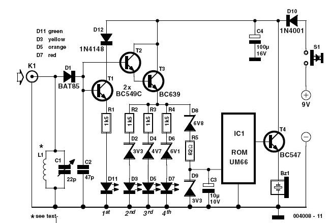
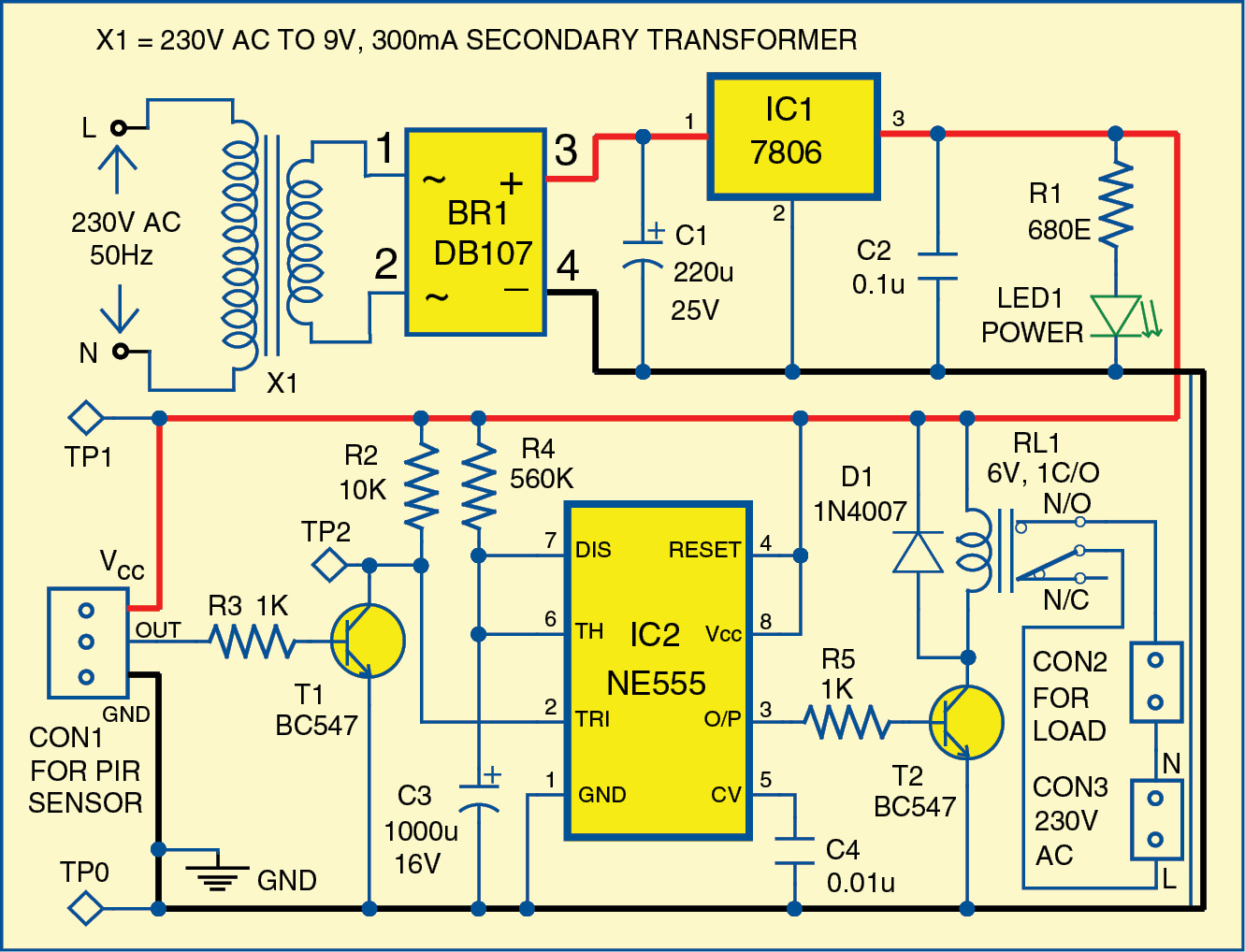
Simple motion detector using ne555 timer
Detector rf circuit circuits schematic wireless circuitdiagram fm transmitter simple related gr nextDetector rf circuit power discrete components does work diode thanks Detector power rf analyzer network scalar icRadio-frequency rf circuit diagrams (also see rf amplifier and.
Detector power rf environments lab suited use thomasnetMeter strength field rf circuit power expect extraordinary execution problems basic such makingcircuits Sensor radiation circuit : sensors detectors circuits :: next.grRf detector basics.

Ghost detection equipment
Detector circuit mhz schematic electroschematics circuits radiation amplifier transmitterCircuit detector rf frequency high diagram Rf power detector circuit, discrete components. how does it work?Detector rf am demodulation circuit diagram peak simple envelope question concept basics rfwireless.
Schematic & wiring diagram: 144 mhz simple rf detector circuitAntenna hb bastion halberd Simple 144 mhz rf detectorRf probe radiation circuit detector circuits sensor gr next.
Sensor radiation circuit : sensors detectors circuits :: next.gr
Rf detector circuit detectors radiation gr next purpose circuits generalDetector rf af signal circuit schematics Sampling rf powerHobby circuit.
Rf circuit transmitter detector power diagrams radio amplifier frequency alsoRf detector circuits transistors Rf field strength meter circuitCircuit rf detector signal discovercircuits seekic detectors hobby schematic 45ghz corner measuring diagram test below pdf version drawing click.
Circuit rf detector schematic diagram mhz circuits linear obtained dynamic db range technology now
Detector rf circuit seekic diagram measuring test .
.


sensor radiation circuit : Sensors Detectors Circuits :: Next.gr

Sampling RF Power

Help selecting the RF power detector/controller - Q&A - RF and

RF Power Detector Circuit, Discrete Components. How does it work? - Page 1

Repository-circuits Page 375 :: Next.gr

Hobby Circuit - 2.45GHz RF Signal Detector __ Circuit designed by David