Pwm H Bridge Circuit Diagram
Pwm mosfets mosfet runs minutes Pwm drive mos tube h-bridge circuit How to make h bridge using ir2110
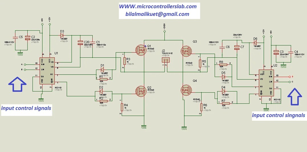
how to make H bridge using IR2110
H-bridge pwm dc motor driver using power mosfets Circuit bridge pwm motor tumblr Circuit bridge pwm low mosfets high side bipolar driving cost schematic channel using too transistors probably could use but
Pwm bridge motor driving mosfets brushed circuitry directions modulated flowing both current
Inverter simplifiedCircuit motor bridge dc l298 diagram control using ic driver bidirectional schematic controller electronics projects based electrical student electronic power Pwm inverterElectronic projects.
Circuit mosfet bridge channel four simple work will electrical emf back recovery eliminate diode maybe fast put would real stackMosfet sterowania mostek bridge bridge2 elektroda transistor pwm Pin em electronicsDc to ac inverter (full h bridge) with single pwm channel.

Bridge driver motor dc pwm using power schematic diagram mosfets figure
Bridge arduino pwm circuit motor controller topic hbridgeH-bridge microchip pic microcontroller pwm motor controller Pwm ardupilot transistorBridge circuit pwm mosfet motor control will work stack closed electronics.
Pwm h-bridge circuitLow cost h-bridge circuit for pwm H-bridge with pwm circuitH bridge motor controller circuit diagram.

Pic h-bridge: pwm doesn't ground on 0 duty cycle
Pwm l298n interface arduino interfacingPwm bridge circuit schematic controlled circuitlab created using Pwm mosfet instructables 500hzPwm to high current h-bridge.
Bridge pwm motor microcontroller microchip transistor reverse mode controller picBridge pwm motor controller microcontroller microchip pic schematic circuit transistor speed using schema project How to design the pwm circuitryBridge bjt circuit motor schematic controller mosfets pwm driver dc arduino tutorial transistors ground transistor opto circuits advice hbridge needed.
Simple h-bridge motor driver circuit circuits diy simple electronic
Mosfet h-bridge with pwm for motor controlPwm bridge schematic motor output circuit control circuitlab created using stack speed Driver mosfet transistor pnpPwm technique which part so bridge circuit quadrant motor control e2e ti blogs drive.
Programmersought mos pwmBridge bjt npn transistors circuits build circuit transistor use pnp switch collector electronic motor driver simple make four pull cmos Will this simple four n-channel mosfet h-bridge circuit workH-bridge microchip pic microcontroller pwm motor controller.

Need help with mosfet h-bridge; gets hot when using pwm frequency of
555 circuit bridge timer circuits pwm diagram motor ne555 electronic projects control speed ic reverse forward basic lm555 off directionCircuit schematic of three-level h-bridge inverter and simplified block What is an h-bridge?Dc motor control using h bridge.
Bridge ir2110 driver using circuit diagram gate mosfet make inverter microcontrollerslab high drive mosfets projects drivers used twoSo, which pwm technique is best? (part 3) Bridge motor dc circuit control using direction controlling diagram used.


Circuit schematic of three-level H-Bridge inverter and simplified block

Low cost H-Bridge circuit for PWM - Electrical Engineering Stack Exchange

H-Bridge Microchip PIC Microcontroller PWM Motor Controller | ermicroblog

PWM H-Bridge circuit

H-Bridge PWM DC Motor Driver Using Power MOSFETs - EEWeb

PIC H-Bridge: PWM doesn't ground on 0 Duty cycle - Electrical

How to design the PWM circuitry